• +380990100901
  • +380672171677
  • +380674654516
  • mail@general.energy

23.August

Overview of VOL-40.5 Double-Pole Insulated Voltage Transformers: Reliable and Efficient for Outdoor Installation
https://general.energy/wp-content/uploads/2024/08/vol_1a.jpg

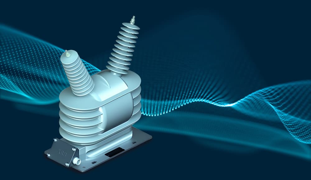
Modern power networks demand high measurement accuracy and resistance to environmental conditions. The VOL-40.5 voltage transformers are an optimal solution for outdoor pole-mounted installations, designed to operate in challenging environments. They provide reliable phase-to-phase voltage measurement in medium-voltage networks, offering a combination of high performance and durability.

Main Features and Benefits

VOL-40.5 transformers are manufactured using advanced materials like hydrophobic cycloaliphatic epoxy (HCEP). This material offers excellent protection against arcing, ozone, and UV radiation, making it ideal for harsh environments. Additionally, HCEP has hydrophobic properties, significantly reducing the risk of overvoltage when operating in humid conditions.

Parameter name Units Parameter name
Maximum voltage Um (root mean square value) kV 40,5
Nominal withstand voltage of industrial frequency (current value) kV 95
Nominal withstand voltage of lightning impulse (peak) kV 200
Rated frequency Hz 50
Rated primary voltage Un kV 38
Voltage factor l,2xUn/continuous
Maximum secondary windings 2 (max. 2 secondary windings with voltage range: 100-120 V, other voltages on request)
Rated secondary voltage V 230
Maximum rated power/class VA/cl 50/0.2; 100/0,5; 200/1; 500/3, 3P или 6P
Power with temperature limitation VA 700
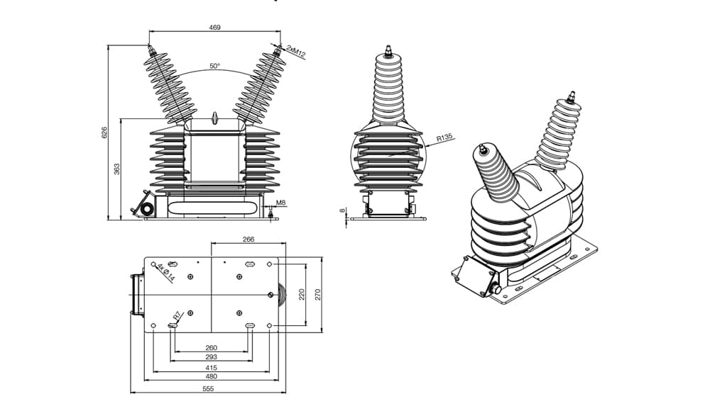
Length of the leakage path mm 1325
Weight kg 70

The VOL-40.5 voltage transformers offer the following key advantages:

  • High Resistance to Environmental Factors: Resistant to aggressive environments and corrosion, ensuring a long service life.
  • Reduced Weight: Design optimization has resulted in significant weight reduction without compromising performance.
  • Reliability in Harsh Conditions: With an operating temperature range from -40°C to +40°C and resistance to contaminants, these transformers are versatile for various climatic zones.

Purpose and Application Scope

VOL-40.5 transformers are designed to measure phase-to-phase voltage in networks up to 24 kV. Typically connected in a ‘V’ configuration, they are the primary solution for outdoor power systems. Models with one or two secondary windings are available, allowing customization to meet specific user requirements. During operation, one terminal of the secondary winding must be grounded to ensure safe operation.

Design Features and Materials

VOL-40.5 transformers feature a robust design with high dielectric insulation. The primary and secondary windings are made using specialized winding techniques to ensure uniform voltage distribution and minimize losses. The windings and core are encapsulated in HCEP, providing excellent protection against mechanical damage and environmental effects.

Installation and Connection

Installing VOL-40.5 transformers is straightforward, thanks to a convenient base plate made of corrosion-resistant aluminum. The removable junction box, rated at IP 54, simplifies installation and maintenance. The secondary terminals can accommodate conductors with cross-sections ranging from 2.5 mm² to 6 mm², offering flexibility in wiring. The terminals are galvanically coated, ensuring corrosion resistance and reliable connections.

Operating Conditions and Additional Features

VOL-40.5 transformers are designed to operate in environments with dust, smoke, corrosive gases, or high humidity. They can be used in conditions ranging from -40°C to +40°C and altitudes up to 1000 meters above sea level. Special models can be produced for operations outside the standard parameters if required.

Warranty and Test Reports

Each transformer undergoes rigorous testing, with the results stored electronically and available to customers upon request. The manufacturer provides a 24-month warranty from the date of commissioning, but no more than 36 months from the date of purchase. The warranty covers manufacturing defects, provided that transportation, storage, and operational guidelines are followed.
VOL-40.5 voltage transformers are an effective solution for outdoor power systems. Combining reliability, durability, and ease of installation, they are the ideal choice for professionals seeking dependable equipment for harsh environments.

Manual

Brochure

21.August

Overview of KOLA 06J2 Current Transformers. Reliable and Functional Solutions for Power Network Protection

https://general.energy/wp-content/uploads/2024/08/vol_1a.jpg

The KOLA series current transformers provide an effective solution for measuring residual currents in three-phase power networks. Thanks to their unique design, these transformers are ideally suited for use with earth fault relays, making them an essential component in enhancing the safety of electrical installations.

Main parameters

Parameter name Units Parameters
Nominal voltage kV 0.72
Isolation test voltage 50 Hz, 1 min kV 3 (1EC 60044-1)
Nominal frequency Hz 50
Nominal primary current A 50; 100; 200; 300; 2000
Nominal secondary current A 1; 2; 5
Accuracy class 10Р10; 0.2
Nominal thermal current A 60; 120; 240; 360; 2400
Short-time current (1 s) kA 3; 6; 12; 18; 120
Maximum withstand current kA 7,5; 15; 30; 45; 300
Secondary terminals for 6 mm2 cable
Operating temperature °C -5 — +40

Key advantages of KOLA current transformers

Variety of sizes: Up to 497 x 300 mm.

Split core versions for easy installation.

Ease of installation: Fixable via fixing points in the housing.

Compact dimensions: Height 90 mm.

Reliable connections: Two secondary terminals ensure efficient communication with external systems.

KOLA transformers are designed to measure the sum of three-phase currents in cable systems. Under normal conditions, this sum is zero, but in the event of an earth fault, it corresponds to the residual current that is transferred to the secondary winding. These transformers are commonly used with static relays for earth fault protection, providing reliable monitoring and control of power networks.

Design and Materials

KOLA transformers feature a toroidal core that can be split open, allowing for installation without disconnecting the cable. The two halves of the core are secured with four bolts, ensuring accurate alignment and stable operation. The secondary winding is encapsulated in high-quality resin, offering excellent electrical and mechanical properties.

Installation Process

The installation of KOLA transformers is tailored to the specifics of the site. Ring-type transformers easily integrate into cable systems, while rectangular models can be installed in a variety of electrical cabinets. During installation, it is important to avoid interference from currents in cable sheaths and to ensure proper grounding.

Selecting the Right KOLA Transformer

When choosing a transformer for earth fault relays, consider the window size and core design. The number of turns in the secondary winding should be selected based on the relay’s requirements and the expected magnitude of the earth fault current.

The correct operation of the earth fault protection relay can be easily verified using a test winding on the transformer, allowing for testing at currents up to 6 A.

Warranty Conditions

The manufacturer provides a warranty of 24 months from the date of commissioning, but no more than 36 months from the date of purchase. The warranty covers defects due to manufacturing issues but does not include damage caused by improper transport, storage, or failure to follow operating instructions.

KOLA current transformers are a reliable choice for those seeking an effective solution for measuring residual currents and protecting power networks from earth faults. Their flexible design, ease of installation, and adaptability to various conditions make these devices an optimal choice for use in industrial and power generation installations.

With KOLA series transformers, you get high measurement accuracy, easy installation, and long service life.

Brochure

Manual

21.August

Overview of KOLA 06D2 Current Transformers. Reliable and Functional Solutions for Power Network Protection

https://general.energy/wp-content/uploads/2024/08/vol_1a.jpg

The KOLA series current transformers provide an effective solution for measuring residual currents in three-phase power networks. Thanks to their unique design, these transformers are ideally suited for use with earth fault relays, making them an essential component in enhancing the safety of electrical installations.

Main parameters

Parameter name Units Parameters
Nominal voltage kV 0.72
Isolation test voltage 50 Hz, 1 min kV 3 (1EC 60044-1)
Nominal frequency Hz 50
Nominal primary current A 50; 100; 200; 1000; 1200; 1800
Nominal secondary current A 1; 5
Accuracy class 10P10; 1
Nominal thermal current A 60; 120; 240; 1200; 1440; 2160
Short-time current (1 s) kA 3; 6; 12; 60; 72; 108
Maximum withstand current kA 7,5; 15; 30; 150; 180; 270
Secondary terminals for 6 mm2 cable
Operating temperature °C -5 — +40

Key Advantages of KOLA Current Transformers

Various Standard Sizes: Available with internal diameters of 100 mm and 180 mm.
Split-Core Options: Available for easy installation.
Easy Installation: Ring-type transformers are mounted using a base plate.
Compact Design: Height of only 85 mm.
Reliable Connections: Two secondary terminals ensure efficient connection to external systems.
Purpose and Functionality

KOLA transformers are designed to measure the sum of three-phase currents in cable systems. Under normal conditions, this sum is zero, but in the event of an earth fault, it corresponds to the residual current that is transferred to the secondary winding. These transformers are commonly used with static relays for earth fault protection, providing reliable monitoring and control of power networks.

Design and Materials

KOLA transformers feature a toroidal core that can be split open, allowing for installation without disconnecting the cable. The two halves of the core are secured with four bolts, ensuring accurate alignment and stable operation. The secondary winding is encapsulated in high-quality resin, offering excellent electrical and mechanical properties.

Installation Process

The installation of KOLA transformers is tailored to the specifics of the site. Ring-type transformers easily integrate into cable systems, while rectangular models can be installed in a variety of electrical cabinets. During installation, it is important to avoid interference from currents in cable sheaths and to ensure proper grounding.

Selecting the Right KOLA Transformer

When choosing a transformer for earth fault relays, consider the window size and core design. The number of turns in the secondary winding should be selected based on the relay’s requirements and the expected magnitude of the earth fault current.

The correct operation of the earth fault protection relay can be easily verified using a test winding on the transformer, allowing for testing at currents up to 6 A.

Warranty Conditions

The manufacturer provides a warranty of 24 months from the date of commissioning, but no more than 36 months from the date of purchase. The warranty covers defects due to manufacturing issues but does not include damage caused by improper transport, storage, or failure to follow operating instructions.

KOLA current transformers are a reliable choice for those seeking an effective solution for measuring residual currents and protecting power networks from earth faults. Their flexible design, ease of installation, and adaptability to various conditions make these devices an optimal choice for use in industrial and power generation installations.

With KOLA series transformers, you get high measurement accuracy, easy installation, and long service life.

Brochure

Manual

21.August

Overview of KOKS 24D11 Current Transformers: Reliable Solutions for Precise Measurement and Protection in Electrical Networks

https://general.energy/wp-content/uploads/2024/08/vol_1a.jpg

The KOKS 24D11 current transformers are a modern solution for converting electrical currents in networks with voltages up to 20 kV. They are characterized by high accuracy and reliability, making them ideal for use in power systems and industrial AC installations. These transformers are specifically designed for transmitting measurement data and ensuring equipment protection, providing high stability and efficiency.

Main parameters

Parameter name Units Parameters
Rated voltage kV 20
Highest operating voltage kV 24
Nominal alternating current frequency Hz 50
Rated primary current A 500; 600; 750; 800; 1000; 1200; 1250; 1400; 1500; 1600; 1800; 2000; 2500; 2800; 3000; 3150; 3200; 3500; 3600; 4000; 5000; 6000
Rated secondary current A 1 та/або 5
Number of secondary windings each from 1 to 4
Measurement winding accuracy class 0,2; 0,2S; 0,5; 0,5S; 1; 3; 5
Precision class of the winding for protection 5P; 10R
Rated secondary load VA 1; 1,5; 2; 2,5; 3; 5; 7,5; 10; 12,5; 15; 17,5; 20; 22,5; 25; 27,5; 30; 35; 40; 45; 50; 60; 75; 100; 125; 150

Key Advantages of KOKS 24D11 Transformers

Specialized Design: These transformers do not include a primary conductor but feature primary insulation, allowing them to be installed directly over a conductor or busbar. This makes them an optimal choice for generator terminals and other specialized applications.

Flexible Configuration: The KOKS transformers offer up to six secondary windings for models rated up to 17.5 kV or up to four windings for models rated up to 24 kV, allowing the equipment to be tailored for different applications.

Standards Compliance: The transformers adhere to multiple international standards (IEC, GOST, AS, BS, ANSI, VDE, CSN), ensuring versatility and meeting various customer requirements.

Operational Reliability: High-quality manufacturing and the use of epoxy compounds guarantee long service life and resistance to environmental conditions.

Applications

The KOKS 24D11 transformers are designed for current conversion in electrical networks with voltages up to 20 kV. They are used to transmit signals to measuring instruments and protection devices, as well as in industrial-frequency AC control systems. This equipment is optimally suited for installation in enclosed busbars and integrated switchgear.

Design and Functionality

KOKS transformers are constructed using high-quality epoxy compounds to ensure reliable insulation and durability. All versions feature standardized dimensions, simplifying installation and integration into existing systems.

A distinctive feature of KOKS transformers is their single-phase busbar design, where the busbar installed within the transformer serves as the primary winding. This reduces installation and operational costs while enhancing system efficiency.

The number of secondary windings can range from 1 to 5 (up to 10 secondary terminals), depending on the required measurement accuracy, protection level, short-circuit currents, and other technical parameters. This customization allows the transformer to be tailored to specific customer requirements, ensuring maximum efficiency and accuracy.

Installation and Operation

The transformers can be mounted in any orientation, making them convenient for various installation conditions. Standard fasteners with screws (M10 or M18, depending on the model) are used for mounting. All connections must be tightened to specified torque levels to ensure reliable and safe operation.

The secondary windings are protected by a terminal block with a plastic cover that can be sealed, providing additional protection against unauthorized access. All unused windings should be short-circuited and grounded during operation to ensure safe functionality.

Standards and Compliance

KOKS transformers are manufactured according to international standards such as IEC, VDE, ANSI, BS, GOST, and CSN, ensuring their compatibility with the requirements of most markets. Additional standards can be applied upon request.

KOKS current transformers are a high-tech solution for measurement and protection systems, offering flexible configuration, high reliability, and adherence to international standards. They are ideal for use in power and industrial networks, ensuring stable and safe operation of equipment.

Manual

Brochure

21.August

Overview of the TPO Series Current Transformers: The Reliable Solution for Outdoor Applications

https://general.energy/wp-content/uploads/2024/08/vol_1a.jpg

TPO series current transformers, featuring molded insulation made from hydrophobic cycloaliphatic epoxy resin (HCEP), are an optimal choice for measurement and protection applications in outdoor environments. Thanks to innovative materials and thoughtful design, TPO transformers deliver high reliability, durability, and protection even in extreme climatic conditions.

Key Advantages of TPO

Resistance to External Factors: HCEP insulation offers high resistance to ultraviolet radiation, ozone, and arc faults, ensuring stable operation even in outdoor environments.

Hydrophobic Properties: The transformer surface repels moisture, making these units ideal for humid environments and ensuring reliable performance in the harshest climates.

Multifunctionality: The transformers can be equipped with up to four secondary windings, customizable for different applications—such as measurement, protection, or special testing.

Main parameters

Parameter name Units Parameters
Nominal primary current A 150
Primary current switching A 600 – 1200
Nominal secondary currents A 5;1
Rated frequency Hz 50
Insulation levels kV 36/70/170; 38.5/80/180; 40.5/95/200
Nominal short-term thermal current [1s] kA 100
Max. rated load/class VA/cl 3 – 60/0,2;0,2S;0,5;0,5S;1;3;5P;10P
Ambient temperature °C -60 — +55
Reconnection Primary or secondary

Purpose

The TPO series current transformers (models 70.11, 70.12, 71.11, 72.11, and others) are designed for operation in electrical networks up to 35 kV and are suitable for both measurement and protection circuits. These transformers are ideal for outdoor use in moderately cold climates, making them a versatile solution for a wide range of outdoor electrical installations.

Design Features and Operation

To protect against external factors, the transformers are made from hydrophobic cycloaliphatic epoxy resin (HCEP), which provides mechanical strength and reliability. HCEP offers excellent protective properties against ozone, UV radiation, and arc faults.

The TPO series transformers can be fitted with one to four secondary windings, which can be used for measurement, protection, or specialized applications. Grounding one of the terminals of each secondary winding ensures safe operation.

Configuration and Installation

The TPO transformers feature a robust housing secured by four bolts. Suspension lugs are included for easy transportation and installation. The secondary windings are enclosed in a sealed compartment with a hermetically sealed lid, providing additional protection from environmental factors.

The transformers can be installed in any position (vertical, cantilevered, or inverted), offering flexibility in placement. A junction box with a PG21 cable gland is included for easy connection and is an integral part of the design.

Quality Assurance

TPO transformers meet the requirements of IEC 61869-2, ensuring high reliability and accuracy. All test results are stored electronically and are available upon customer request.

Advantages in Use

The TPO series current transformers perform exceptionally well in applications involving frequent line switching and overvoltages. Encapsulated in HCEP, they provide reliable protection and stable operation even in challenging environments such as coastal or polluted areas.

The TPO series transformers are a dependable solution for measurement and protection tasks in power grids up to 35 kV. High-quality materials, resistance to external factors, and adaptability to diverse requirements make these transformers the ideal choice for outdoor applications in any environment.


20.August

Overview of TJO Series Transformers: Reliability, Resilience, and Efficiency in Harsh Environments

https://general.energy/wp-content/uploads/2024/08/vol_1a.jpg

The TJO series transformers, manufactured using hydrophobic cycloaliphatic epoxy (HCEP), offer high resistance to external factors and are highly reliable in outdoor environments. HCEP not only provides excellent protection against arcing, ozone, and UV radiation but also possesses high mechanical strength, ensuring the equipment’s durability and safety even under challenging operating conditions.

Main Advantages of TJO Transformers

Measurement Accuracy: TJO transformers are specifically designed for phase voltage measurement, offering high load capacity while maintaining the required accuracy class.

Resistance to Environmental Factors: The hydrophobic HCEP material performs exceptionally well in wet environments, minimizing the risk of arcing and protecting the equipment from contamination.

Optimal Solution for Measurements: The application of ResiVolt technology effectively counters fast transient overvoltages (VFTO) that can occur during the operation of inverters or switchgear.

Purpose and Application

The TJO 7 series voltage transformers are ideal for use in electrical networks up to 35 kV. They are used in both measurement and protection circuits, ensuring reliable performance in various conditions, including aggressive environments and coastal areas.

Technical Features and Design

The TJO series transformers feature a single primary winding, with one side earthed during operation and the other isolated from the ground. Most models come equipped with two secondary windings: one for measurement or protection circuits and the other for open-delta connections in three-phase systems.

All secondary winding terminals are housed within a molded, hermetically sealed enclosure that protects against external factors. The design facilitates easy installation with integrated hanging loops and bolted connections for simpler transportation and setup. Additionally, the transformers offer flexible application options with two primary winding voltage settings and a switch on the secondary side.

Main parameters

Description of parameters Unit Parameters
Rated primary voltage kV 20:√3; 22:√3; 27:√3; 30:√3; 33:√3; 35:√3
Rated secondary voltage V 100:√3; 110:√3
Rated voltage of an open triangle circuit V 100:03; 110:03
Rated frequency Hz 50
The greatest work stress kV 40,5
Test voltage of industrial frequency, 1 min. kV 95
Lightning impulse test voltage (peak) kV 200
Maximum load/accuracy class — measuring winding VA/cl 50/0.2; 100/0.5; 150/1
Maximum load/accuracy class — additional winding VA/cl 200/3P or 6P

Reliability and Compliance with Standards

The TJO series transformers are engineered to meet international standards (IEC, EN, VDE, ANSI, BS, DSTU), ensuring high reliability. The HCEP encapsulation provides superior performance even in contaminated and humid environments, while the increased creepage distance significantly reduces the risk of electrical breakdown.

Versatility in Installation

TJO transformers can be mounted in vertical, cantilevered, or inverted positions. For enhanced reliability, it is recommended to use strain relief devices when connecting cables. The aluminum base plate is compatible with the dimensions of other popular models on the market, simplifying the integration of these transformers into existing systems.

The TJO series transformers are the ideal solution for ensuring stable operation of power supply systems under difficult conditions. Their versatility, resistance to environmental factors, and proven reliability make them an excellent choice for technicians seeking long-lasting, dependable equipment.

Brochure

20.August

Overview of GE GL 312 F1/4031 P and GL 312 F3/4031 P Live Tank Circuit Breakers

https://general.energy/wp-content/uploads/2024/08/vol_1a.jpg

The GE GL 312 F1/4031 P and GL 312 F3/4031 P series of live tank circuit breakers are designed for outdoor installation and offer high reliability even under extreme operating conditions. Specifically engineered for low-temperature environments (down to -60°C with a gas mixture and -40°C with pure gas), they incorporate advanced engineering solutions to ensure reliable performance in harsh climates and high-seismic regions.

Key Features and Components

These circuit breakers leverage the latest technologies to significantly enhance efficiency and reliability. A standout feature is the implementation of a double-motion system, reducing energy consumption by 65% during operation. Additionally, the overpressure protection system provides a safe working environment for personnel and substation equipment.

Key components include:

  • Breaker Chamber: Features dual-motion technology and a self-blast system, ensuring stable operation during switching.
  • Pressure Relief System: Offers additional protection for substations and personnel in emergency situations.
  • Temperature-Compensated Status Monitor: Equipped with a two-stage sensor and a three-color indicator for precise monitoring of equipment status.
  • SF6 Check Valves: Installed on each pole to ensure safe handling and management of gas.
  • Aluminum Housing and Galvanized Parts: Provide durability and resistance to corrosion.
  • Spring-Loaded Mechanism with External Position Indicator: Facilitates quick assessment of the switch condition.

Technical characteristics

Rated voltage 145 kV
Lightning surge test voltage (phase-to-ground) 650 kV
Rated frequency 50 Hz
Rated normal current 3150/4000 A
Short circuit trip current rating 40 kA
Rated switch-on current (electrodynamic stability) 104 kA
Duration of short-circuit current flow 3 s
Custom switch-off time 28 ms
Total switch-off time 1.5
Switch-on time < 70 ms
Operating temperature (SF6) -40 °C – +40 °C
Installation height above sea level 1000 m

Easy Installation and Maintenance

One of the advantages of this series is the ease of installation. The GL 312 F1/4031 P and GL 312 F3/4031 P circuit breakers are delivered pre-assembled, significantly reducing commissioning time. Maintenance is also simplified thanks to extended inspection intervals. Additionally, the design allows for the breaker chamber to be serviced without disassembling the entire pole, greatly streamlining maintenance tasks.

Standards Compliance and Certification

GE equipment undergoes rigorous testing in accordance with international IEC and ANSI standards. All development and production stages strictly adhere to ISO 9001, ISO 14001, and OHSAS 18001 standards, verified by regular audits. This guarantees that the final product meets the highest quality and reliability standards.

Benefits for Technicians

Choosing GE’s GL 312 F1/4031 P and GL 312 F3/4031 P circuit breakers is an investment in long-term equipment reliability. With innovative technology, these circuit breakers can perform in even the most demanding environments, making them ideal for businesses looking to minimize downtime and ensure continuous operation of critical systems.

GE’s GL 312 F1/4031 P and GL 312 F3/4031 P series live tank circuit breakers are the optimal choice for businesses needing reliable, low-maintenance, and high-performance outdoor equipment.

Brochure

20.August

ABB VD4/P 12.25.25 P275 Series Circuit Breakers Overview: Technology, Reliability, Innovation

https://general.energy/wp-content/uploads/2024/08/vol_1a.jpg

The ABB VD4/P 12.25.25 P275 series circuit breakers offer a state-of-the-art solution for medium-voltage electrical networks. These breakers combine advanced developments in vacuum interrupter technology with innovative approaches to circuit breaker design and manufacturing. The equipment is highly resistant to shock, dust, and humidity thanks to a special design that ensures reliable protection of the circuit breaker.

Main Features and Advantages: Withdrawable Circuit Breakers for Switchgear

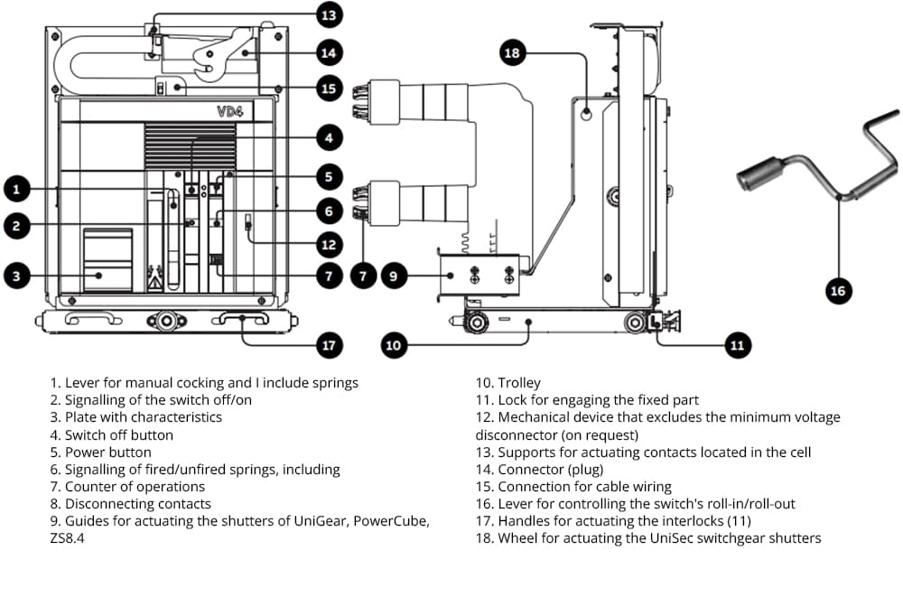
The VD4/P 12.25.25 P275 circuit breakers are designed for use in switchgear systems with rated voltages up to 12 kV, such as UniGear ZS1, UniSec, and PowerCube. Their design allows for quick and easy installation using a trolley with handles for convenient maneuvering and a dedicated control mechanism.

Main features

Minimum voltage kV 12
Nominal frequency Hz 50
Nominal thermocurrent A 2500
Variable capacity and short-time current and short-time current and short-time current kA 25
Switching capacity kA 40
Allowed short-current time s 3
Weight kg 105

Integration with Electrical Systems

The VD4/P series breakers feature standardized connectors for connecting electrical equipment, making them versatile for various projects. All electrical connections and accessory installations are accessible from the front, simplifying both installation and maintenance.

Operating Principle and Reliability

High-Performance Vacuum Interrupters
The contacts of the VD4/P circuit breakers are housed in a vacuum chamber, ensuring fast and efficient arc quenching when opening. Thanks to the special contact geometry, uniform arc distribution is achieved, minimizing its impact on the contacts. This significantly extends the lifespan of the equipment and reduces the risk of damage even under high short-circuit currents.

Control Technology
The breakers are equipped with a spring-charged EL-type actuator, which ensures high-speed operation and reliable switching and tripping. The control mechanism is designed for ease of use and can be customized as needed.

Applications

VD4/P circuit breakers are an optimal solution for protection and control in electrical distribution networks, transformer and distribution substations, as well as in power lines and generators. They are widely used across industries to control cable and overhead lines, motors, and capacitor banks.

Maintenance and Durability

One of the key advantages of the VD4/P series is its low maintenance requirements. The control mechanism and vacuum interrupters require minimal inspections and repairs, reducing operational costs and enhancing the overall system’s reliability. All maintenance operations are performed simply and safely, with a focus on safety procedures.

ABB’s VD4/P 12.25.25 P275 circuit breakers offer a versatile and reliable solution for a wide range of power applications. Their user-friendly design, dependable vacuum interrupters, and flexible customization options make these circuit breakers an excellent choice for various operating conditions.

Catalogue

Documentation

Manual

19.August

Vacuum Circuit Breaker Type OVB-VBF 35 kV: Reliability and Technology in Switching

https://general.energy/wp-content/uploads/2024/08/vol_1a.jpg

The OVB-VBF 35 kV vacuum circuit breaker is designed to control 35 kV electrical circuits in three-phase AC networks with insulated or partially earthed neutrals. It ensures stable operation of the network in both normal and emergency modes at a frequency of 50 Hz.

Construction and Components

This breaker is a live tank type, where the switching mechanism is housed inside insulating porcelain enclosures filled with gas (sf6) or nitrogen under pressure. This solution minimizes the risk of moisture formation and ensures the device’s longevity.

Main Parts of the Circuit Breaker:

  • Pole Assembly: Includes the vacuum chamber, contacts, insulating linkage housed in a porcelain enclosure, and the overall drive mechanism.
  • Actuator Cabinet: Contains a weatherproof spring mechanism and additional equipment such as heating, position indicators, a mechanical counter, circuit breakers, relays, interlocks, etc.
  • Steel Frame: Sturdy corner supports that can be adapted to accommodate additional elements such as current transformers.

Advantages and Features

The OVB-VBF 35 kV circuit breaker features advanced solutions from ABB:

  • Vacuum switching ensures high reliability and durability.
  • It complies with international IEC and Class C2 standards, minimizing the risk of restriking when operating with capacitive loads.
  • Porcelain enclosures are suitable for outdoor use and provide protection against fire and external influences.
  • The simple and efficient spring mechanism requires minimal maintenance.
  • Capability to perform an O-B-O cycle without intermediate recharging.
  • Fast spring compression by the motor (up to 15 seconds).
  • Additional contacts (13 NO + 13 NC) and an optional additional trip coil.

Operation and Maintenance

The circuit breaker is delivered pre-assembled, significantly reducing installation time. Its modular design simplifies maintenance, and the use of modern materials ensures a long service life. If necessary, it can be transported in separate parts.

Testing and Certification

Each circuit breaker undergoes comprehensive testing according to IEC 62271-100, including structural integrity, voltage tests, switching speed, and surge protection, to ensure it meets the highest standards of quality and reliability.

Live-Tank circuit breaker OVB-VBF 36
Standard IEC 62271-100
Rated voltage kV 36
Insulation voltage кВ 36
Испытательное напряжение kV/min 70(dry)/70(wet)
Impulse voltage kVp 170
Nominal frequency Hz 50-60
Rated current A 1250 2000 2500
Symmetrical breaking current kA 25 25 31,5
Short-circuit current (3s) kA 25 25 31,5
Asymmetrical breaking current (% of constant component at t=45ms)kA 35
Switching current kAp 63 63 80
Own switch-off time ms 45
Switching capacity at capacitive currents A 400
Arc burning time ms 5-15
Total switch-off time ms 50-60
Switch-on time ms 75
Dimensions With supports (HхLхD) mm (3090-3840)х900х686
Weight kg 850/900
Absolute pressure N2 kPa anti-condensation 150
Operating temperature °С -25(-40) … +40

The OVB-VBF 35 kV vacuum circuit breaker is a modern solution for efficient switching in demanding environments. With its innovative technology, high reliability, and ease of maintenance, it is the optimal choice for distribution networks and industrial facilities.

Brochure

Catalogue OVB VBF EL3

Catalogue OVB VBF ESH

Manual